In this webinar, we explore the intricacies of designing for injection molded plastics. Our expert will guide you through common challenges and essential design practices, ensuring your designs are primed for rapid prototyping and production. From addressing warpage and shrinkage to optimizing wall thickness and implementing strategic design features, this session equips you with the knowledge and tools needed for success in injection molding with advanced materials.
The webinar also features an in-depth case study where our experts will illustrate how to apply these key principles in a real-world scenario. By dissecting the intricacies of a specific project, attendees will gain practical insights into overcoming hurdles and achieving optimal results in injection molding design. Join us as we unravel the complexities and unveil the strategies that underpin effective design for injection molded plastics.
What you'll learn:
- Strategies for addressing common molding challenges like warpage, shrinkage, voids, and sink marks.
- Guidance on implementing design best practices, including optimizing wall thickness and utilizing draft angles, fillets, ribs, gussets, and bosses effectively.
- Tools necessary to create high-quality, efficient designs suitable for rapid prototyping and production in injection molding with reinforced plastics.
Speakers

Aaron Daniel
Director of Engineering
Alpine Advanced Materials

Jeremy Smith
Business Development Manager
Alpine Advanced Materials
Webinar Transcript
Jeremy Smith:
Right. Hello, and welcome everyone who's joined so far. I'm going to give it a few more minutes for the rest of our attendees to trickle in. In the meantime, I'm going to open a poll just to get some base information on your knowledge of the subject that we're going to discuss today. So please answer the poll and keep in mind. There will be one later in the presentation as well. Alright. So as attendees keep rolling in, we're going to get started here. Just so we're mindful of everyone's time. Thank you to everyone who's filled out the poll so far. I will keep it live for a few more slides as I get through the introduction into what we're discussing today. To give you guys broad strokes, this is Alpine's first webinar, and we are dedicating this topic to advanced design techniques for injection molding, so it's going to be an introduction to designing parts for injection molding. A few housekeeping items before we get started." This webinar is being recorded and will be sent to you following the close of the webinar for your access at any time. And there is also a QA chat box in the zoom window that you can use to type in your questions. I will be keeping an eye on the questions as we move through, and if there's anything that I can answer real time, however, I will try to keep most of the questions. Towards the end of the session that we have planned for a quick introduction to our presenters today me. My name is Jeremy Smith. I'm a business development manager here at Outline. I've been here for about 3 years working in all different industries. And prior to that, I typically or I traditionally worked in aerospace in multiple different facets and roles from raw material, processing all the way through to final good deliveries of a tier, one supplier to aerospace and joining me today and leading the technical discussion of our panel is Aaron Daniel, and I'll have Aaron introduce himself.
Aaron Daniel:
Thanks, Jeremy. My name's Aaron Daniel. I'm the director of engineering at Alpine. My team and I are responsible for everything technical regarding design analysis and upgrade manufacturing parts. I spent 20 years in industry. From aerospace to contract manufacturing, manufacturing domestically and around the world. With a big focus on selecting the right materials for the right applications. Alright, thank you.
Jeremy Smith:
Alright, thank you Aaron and as I talk through this slide, I'm going to close the poll at the end of the slide. So, all of you who have joined, if you have not. Answered our introduction bulk. Please do so. But to give you an idea of who Alpine Advanced Materials is for those who aren't familiar. We are a full-service design and manufacturing partner our preferences deliver to deliver turnkey parts made from injection, molded thermoplastics. Though we have flexibility. In our operations. We provide design services. We provide manufacturing services. We provide post processing services for injection molding goods. We provide machine metal components. So, we are a flexible full-service partner, but our specialties are injected molded thermal black plastics with an intent to convert metallic components to nonmetallic components for light waiting, for environmental resistance, for manufacturing rate, for economics. There are a number of reasons to consider injection molding with high performance, thermoplastics. And that's what we're here to start talking about today is how to consider injection molding for your application, a high-level overview of injection molding. It is a manufacturing process that Aaron will detail the full science of later. But it's advantages or it's scalability the throughput that you see daily production rate is, is obviously a comparative scale, but its throughput is unmatched in the manufacturing world. You are producing parts on the order of seconds in a highly repeatable fashion. You generate a, you know, steel tool cavity. Essentially, that is the negative of your part, and you're able to produce the same part consistently over and over again. And it's also a highly economical manufacturing process, like I said, you're producing parts in seconds from a raw material stock. And when we're specifically talking about converting metallic to non-metallic components, the ability to produce parts at high rates think you know, thousands of parts a week is unmatched with injection molding. And you're comparing to multiprocessing multi setup machines metal components. Compared to added manufacturing, it'll it is also a much more scalable and repeatable manufacturing process, with better results in high performance materials.
Some of the things that we do at Alpine, when considering your switch from whatever manufacturing option to injection molding is, we study the the cost of it, basically the investment in time and economics to develop that steel tool, and that goes through the engineering process which will produce a case study for you today. They walk through how we approach designing apart from a traditional component to the injection molded manufacturing process. But also, some of the more functional aspects of it. The interchangeability of a part. If you're creating a part to drop in as a replacement to an existing system. It's important to maintain all of your, you know, mating services, your load requirements, etc. So, all of those must be considered when changing materials and manufacturing processes. And when you think about designing for injection, molding, there are a number of different aspects to study, and Aaron's going to walk through how we approach it. But the key point to understand here is when you're evaluating different manufacturing methods. Each manufacturing method has capabilities and limitations. Some have favorable processes for giving materials, some have favorable processes for rate. Again, 1,000 parts, you know, in a short order is no large task for injection. Molding, however, for multi-axis setup or complex carbon fiber layout that can be a challenge. So, you have to consider all the aspects of what the part needs to be, what your production schedule needs to be. When evaluating your manufacturing some key terms that we're going to learn about today. Everyone loves vocabulary words. There will be a quiz later. But it might not be over vocabulary. Some of the key terms we're going to learn about today is the tool, which is the, you know, steel construction, or sometimes aluminum construction that constituents the negative cavity that is injected into parts of the tool are the cavity, the core.
And then there are some other features to basic tool or to non-basic tools that are side action slides, lifters, etc. Will give you some more complex features that you can then produce a fully. You know a turnkey part out of a tool some of the key terms are draft angles, fillets, ribs, gutless boxes, etc. And with that I'm going to turn it over to Aaron to start educating us on those key terms and designing for injection. Molding.
Aaron Daniel:
Thanks, Jeremy. So, one of the biggest questions we get is, why does it take so long to make a tool. And why does it cost so much? On the right side, you can see kind of a cross section of a standard tool. It's not just the A plate and the B plate before in the cavity. That Jerry mentioned previously. It's everything else that goes along with it. The tool has to be mounted to injection molding press. The parts obviously have to be made with the primary components of the tool the part has to be ejected. There has to be cooling lines. There's can be hundreds of parts that go into manufacturing, and each one of these parts has to be precision. There can be very much slop or gas. They're very high tolerance, plus resulting in a tool that can take multiple weeks to multiple months to build, depending on the size and scale and features as well as a high cost. And the tool doesn't have to just manufacture a single product most tools that we deal with. We deal with customers that have multiple parts that they're working with on a regular basis. So, in order to help decrease that lead time and decrease the cost, we can put multiple parts in the same tool when it's convenient or if we've got parts where we know we're going to need hundreds of thousands to millions of components in the year, we'll do a multi caddy tool kind of like what you see on the left there, where we still have the individual parts. You have in this in this space, and then you have a, the primary screw, which is a material coming into the tool and the runner system, which is driving the material out to each specific part and then each specific part obviously is molded by itself and balancing these parts, making sure there's even flow from one side to the other side is a critical component in designing tools and running simulations.
Jeremy Smith:
Aaron, quick question, what's the largest tool that you've seen, or that may exist today to give a sense of scale for our listeners.
Aaron Daniel:
So, at Alpine in the past couple of years we've actually molded a 32-inch diameter, Bart. That was an 8-and-a-half-pound shot. Of HX5, in relation to a metallic component. That that would have been machined out of that would have been a 17-and-a-half-pound finished machine part that would been milled from a large bill on multiple sides. But I've also seen tools that have accommodated TV buses. So, every 85-inch TV that people have in their homes. The backside of that is a plastic molded part. That's something that's very commonly made and billions of them are made every year. So, and 85-inch TV bezel tool is going to be on the order of. I don't know a 7- or 8-foot steel platform.
Jeremy Smith:
Alright, thank you. So that gives the scale of the large end, and we can make parts all the way down to little pieces that fit in your hand. So there are a wide breadth of sizes that can be done with injection.
Aaron Daniel:
Right. And then, as Jeremy mentioned, the first thing that we do when we're looking at converting apart from metallic to thermal plastic is looking at the geometry of this is something that's done when you use metallic components, you always want to design your part for the process you're intending to manufacture that the first thing that we look at from molded parts is consistent. Wall businesses. Consistent wall thickness is a in material flow. And, after all, injection, molding is basically a large blue. So, you want the fluid to flow evenly. You want to flow with even pressures as much as possible. and when you encounter challenges with that you have to account for those in different ways or you have to deal with the results. And the case of inconsistent wall thicknesses. You can end up with things like stress concentrations, where you're transitioning from big sections to thin sections, you can end up with porosity, and you can end up with some inconsistencies in the surface of the part depending on the geometry that you're looking for. And what that really leads to is a part that's not going to reach your requirements, more than likely you could end up with more rooms. You could end up with aesthetic features that are rejectable, especially on high value services and you could end up with just some other inconsistent features that maybe the causes later on down the line. But in general, your part is not going to meet the requirements of the drawing of your model and your intended purpose. If you're not following proper design fences.
Next another big challenge with injection. Molding is threat. When you're machining apart perpendicular walls to the bottom places. Those are ideal. Most mills are 90 degrees. So being able to just mill out pockets that simple, it's easy. Everything is 90 degrees to each other injection molding. You have material ability. and then that part has to come out like that. So, you have to be able to eject it. That, the larger the draft enable is, the easier it is to eject that a zoom ease of manufacturing available molders are going to ask for 3 to 5 degrees on average, just to make injection molding easier. It makes the process easier, but that does present additional challenges. But most materials allow you to go down to a much smaller size. Your CDC crystalline low shrink materials like will usually require minimum traction a little bit about one-degree other thermal plastics more on the amorphous side, like your Polycarbon to your ads is, you go down to about half a degree, depending on the size of the part that's being molded and if you decide to add texture to it. So, you're not looking for a poly surface, you're looking for something that's got some fuzziness to it, or a leather grain or wood graining, or something else that's added to the tool. To give that surface some feature you have to add additional draft to that, because basically, all those little features in there are under cuts. And we'll talk about that again when we're talking about the this being a fluid dynamics problem. Just like you would see in a piping diagram or anything like that, you want to make the fluid flow as easy as possible, so no sharp corners everything being radius, because that lets the fluid flow easier, it presents prevents any level of small cavitation on the backside of sharp corners and decreases the overall pressure that is required to multiply. So, you can decrease the size of your equipment. That's when you indulge 200 times to maybe 150 times you. That may be more accessible. It may be something that most shops have in more months.
Jeremy Smith:
Aaron, can you touch on how a stress riser and introducing a stress riser in the part is important, not only from the manufacturing perspective of getting the fluid to flow around a section, but a sharp angle stress riser, say, an injection molded thermal plastic is a little bit different from what you would see out of a machine metal component. Can you describe that for us?
Aaron Daniel:
Yeah, absolutely. So, when you're filling these parts and applying pressure, there's going to be some residual stresses in the part. What these stress providers are going to do is create additional areas like what we saw on the first slide where we had inconsistent walls so it could present an area of high tension or high compression, and that could cause your parts to work. In addition, you have very hot molten material going in very high pressures. So having a sharp angle in your steel and this high-pressure high temperature fluid moving around. It's going to work hard in that part, and at some point, you could have a fracture in your tool. And then a piece of that steel comes off at some part at some point down the line, and every part after that is now going to have that little bit of deformity. And because now, he said, that still is easy.
Jeremy Smith:
Thank you.
Aaron Daniel: One of the biggest challenges that we see in addition to inconsistent wall witnesses is large walls intersecting in the box. So, you get this when you have ribs or gussets that are on the interior of a part and making contact with the exterior primary walls. When this happens, you have a large section there, and the material has to pull. I mentioned everything is in a molten condition, so when things cool, they sure depending on the level of shrinkage in a part you can end up with an aesthetic feature on the outside of a part called the same, which is basically like a little bit. The best way to minimize this is obviously removing the brimful. That's it. If you can. If not, then the wall thickness needs to be meetings. And ideally, you want to target a 40 to 60%. Max wall thickness based on the thickness of a wall that is intersecting and your higher strength materials. Again, your mortgage materials, your Pcs, your Abs's some nylons. You're going to want to target the 40% rate because they shrink a lot less or they shrink a lot more than your higher performance materials, your Pds, your HX5's your high strength nylons, those you can usually tend more towards the 60% side. But it's still something that needs to be watched and needs to be evaluated, depending on the aesthetic response, so that when you do have walls and rooms ribs and dust, it's in your garden. At some point you may encounter areas where they intercept. When this happens, you, there's no way really around it, even by shrinking the wall thicknesses to get away from having a fixed section at that end of session. So, the best way that we really deal with that is to just put a core PIN in those areas. It's a, it's a hole that goes down and basically decreases the wall thickness artificially in those areas and leading from that. When you do add a core pen or hole, or a mountain feature in a part.
Really what you want to do if you're not going all the way through that part, you want to have that whole go at least subservice about 30% the thickness of that part and that will help decrease your wall thickness. It'll give you some additional, basically clearance for lack of a better term maintaining some consistent wall thickness as well. Main, while not increasing the intercepting wall size another challenge that we see with this is when you're machining apart. You see that across the corner is probably one of the more preferred ways to create installation places where you're going to mount a cover in the top, putting it in the corner easy. The mill just runs around that area and build up. But what you undoubtedly and end up with is a large wall intersecting actually 3 services at that point. You've got the 2 exterior walls here, and then you've got the wall at the bottom as well on the bottom sets. So, from an injection, molding standpoint, the better option is to actually inset that mounting feature to the part sorry and connected if need be. If you need that extra string to the walls with a rib with a gusset. You can also add additional rib regions on the inside to add additional strength, if need be. But the views, one of the preferred ways to add a mountain to an inertial part. And then here you mentioned side actions an A side and a B side are the 2 parts that you're always going to make encounter when your injection holding, they create the exterior surface, the exterior volume of your plan. Anything that is not that cannot be seen from the H site or B side has to be done with a side action or a secondary bus. So, if I add in the side action into a tool you are. Going to add some time to the tooling leave time, and you're going to add some additional costs. Side actions can be as simple as the lifter. If that's a mechanical mechanism inside the tool that moves out of the way as the tool is opening it can be as complicated as a slide which can be a solenoid activated feature that is, activated moved in, moved out based on the cycle time of the part, and you can even add these on top of each other. We actually perform or design tools where we have slides on top of slides or lifters on lifters, or the very complicated features.
When you're doing a high-volume part. This is usually the best time to do to evaluate this, whether or not you can get a ROI on it, is if I put the action in the tool. Yes, it's going to increase the cost. But if I have to make that feature as a secondary operation, whether it's in machining a whole or milling out something special. That's going to add additional time on the recurring side while, so it'll increase the cost of that increase time of your return while saving a little bit on your non recordings. So, it's kind of a balance between the 2 on whether or not you want to do this as part of the tool or not. Part of it.
Jeremy Smith:
And that's an important part of the evaluation because it can impact the economics of your investment to create a tool. But it also impacts the lead time to create a tool. The more actuation features you introduce, the longer it takes to produce that first part.
Aaron Daniel:
We do have undercuts. There are special ways that we can get around them in some cases. As you see there in the top 2 pictures on the left. We have a standard underpot which will be created by putting a lifter in the tool, since it's a simple under that feature. If we wanted to take that out, and there's no challenges with the geometry on the backside of that wall that it's intersecting. We can always create a cut out on the underside of it, so that way. When looking at the part from the top or the bottom. So, you're inside your B side, you can see all the features of that point, and that tells me that I don't have to add any exact side actions in the bottom view. There, on the left, we have something similar. It's something that can be done with 2 lifters in it, one on each side the electric can be from the inside or the outside, depending on your aesthetic requirements again. Those are going to add all those are going to have time. If it's possible that little window can be wrapped around the edge. And now again I can see all the features of that part from the top or the bottom within. I don't need any sign and in some special cases we can add a an undercut, something that looks like an undercut feature to the tool. The way this happens is it's called a shut off, so you would have pieces from the A side and pieces from the B side of the tool when the tool is closed, they shut off on each other again, wise, all shut off. And they create a basically a piece of steel in that area. And the material will not fill that area, builds everything around it just like it would if that feature built into just one side of the team. What you do end up with is a party line that you see there on the bottom right where those 2 pieces do meet. This can only really be done in certain areas, certain geometry. It requires really a shut off angle of a minimum of about 3 degrees, but usually 5 to 7 degrees of angle is preferred in that area. So, something that's got a relatively vertical plus or minus one degree surface is not going to be extended for that. So, you'd really need something that's draft it out has some angle to it of about 5 or 7 degrees.
Jeremy Smith:
Yeah, it's a balance of increasing a minor feature to decrease the major feature of a tool to, you know, mitigate adding several different actuations to a tool by slightly changing the angle of your given part to account for a feature such as app.
Aaron Daniel:
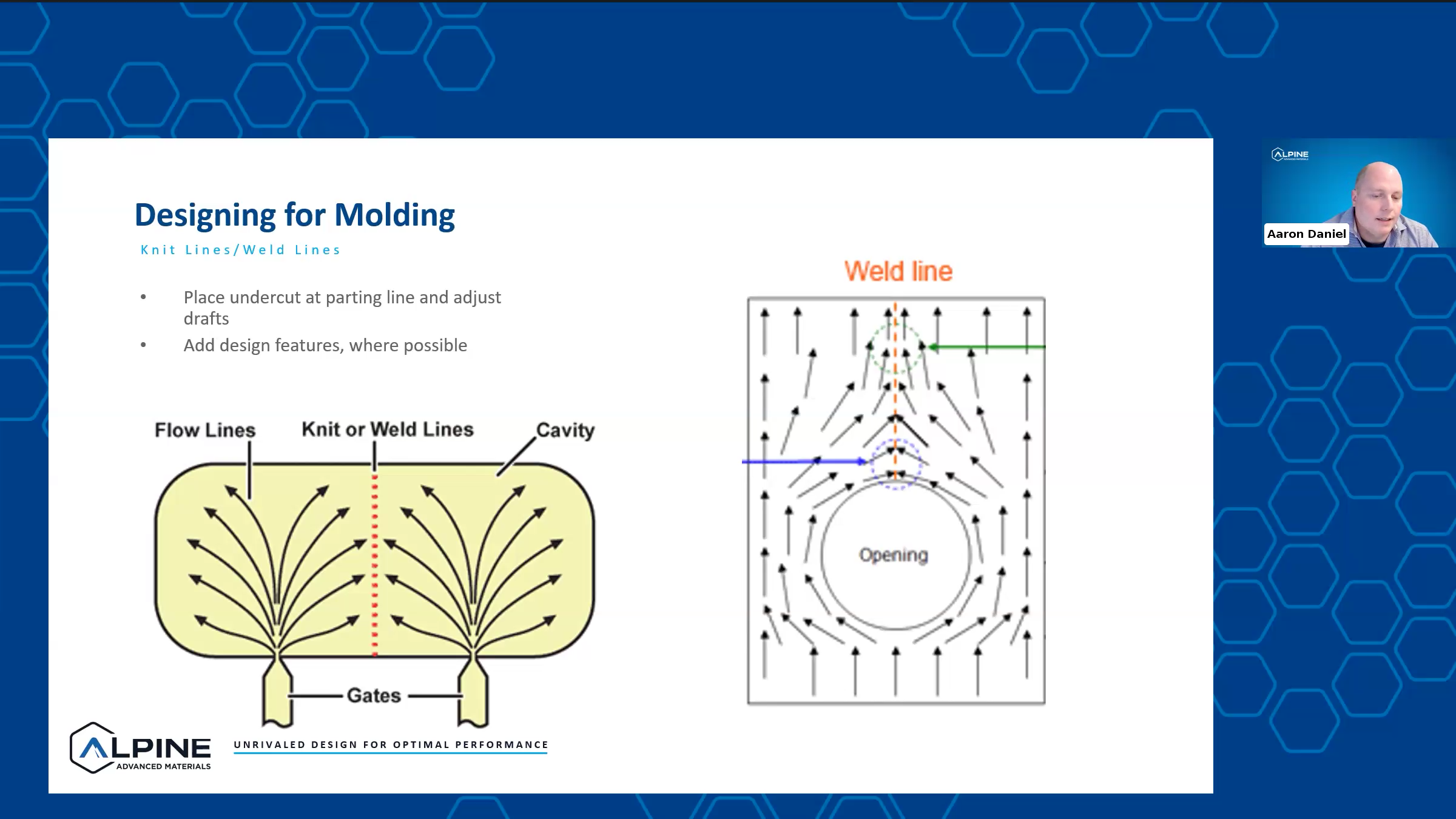
Right. And again, that goes back to? Can I do this? Does that affect the geometry of my part? Do I care that affects the geometry of my part, or would I prefer to spend a little bit more money and time on putting lifters or slides in the part. Another challenge from injection. Molding is niplines or lowered ones. So, whenever you have 2 areas of fluid flow meeting each other. you're creating an area that is really non. So, in the area on the left. This would be something you would see in a big part where we have multiple days. And this would be something we can talk about later as well. We have 2 areas of fluid flow coming in. They're going to meet in the middle and create a line that has not mixed. This really only presents challenges in film materials somebody has to get glass to carbon, because I'm not getting an interchange of that material. Very well at that area unless I've got a very hot note front, and it's usually going to be a good distance away from where the materials are starting to come together. So, it's going to be downstream, part of it. We see this more often in parts where we have polls. So, we have, like the view on the right. We have all of our material coming from one side. We have a hole or a gap in the bar. The material close around it rejoins on the backside. And then in that area, just on the back side of that hole, we're not gonna have a good blend of any kind of filler materials. In part, it's going to be a slightly weaker area. And then about one diameter away from that, you're going to start to see a good homogeneous mixture. But so, this is where you would consider the performance of the part. Is there a very low on this? If there is, maybe I want to design it so that I have the fluid flowing from the other direction and put the bearing load on the surface. That's going to be very much where I've got the fluid and not on the side of that. I'm going to have a little bit weaker strength in those scenarios. And another aesthetic feature that you might see in advance is dark materials that have a lot of glass, Bill, you may see something that looks like some white streaking in the park. And that really what that really is visibility of the glass on the surface at that point. So, it's not really a performance problem in those areas. If you're just seeing kind of how it flows, because you've got some additional turbulence in the area where that glass flowing.
Jeremy Smith:
Alright. So, to summarize. There are a lot of aspects to consider. When evaluating a part for injection. Molding the major design features that Aaron just walked through. Are your wall thicknesses, the draft angles ribs, fillets, bosses, some more finer features of a part. But I hope that you guys were able to catch on to some of these key terms. We're going to walk through a case study here in a second that might re-establish some of these terms and hopefully educate you guys on how Alpine approaches, designing a part that was made for tradition or a different manufacturing process, and migrating it to injection, molded with high performance, thermal plastics and just a little note on material or parts of material considerations for injection molding the first thing we're going to look at as your part size like Aaron mentioned, you could get anything from the bezel of a of a large ad, 4 inch television screen or television, the back bezel all the way down to tiny little parts that fit in your hand. So, evaluating the size of your part, whether it fits into the injection, molded framework, or you know the envelope as a good part, we're not going to be injection molding wings for an unfortunately, I'd like to, but Aaron will let me do that. Further considerations are the geometric complexity of your part. It's highly favorable and injection rolling to do complex featured parts. You see, all the parts pictured here are all you know, traditionally tough to machine the armrest on the left is traditionally an injection, molded part because it has all those fine features that you either couldn't or wouldn't do out of a machine process. The bulkhead you see in the middle has a lot of details that would again be difficult and time consuming to machine out of a billet. So, weighing those options from a geometric complexity. The more complex your part, the more favorable it is for injection, molding, and also can you incorporate other parts connected to your part, if you're looking at a single component in an assembly. But there are components that are either, you know, bonded to it manufacturer, tap them to it with hardware, etc. Is there potential to incorporate that into one part, because this manufacturing process allows for that complex geometry. So, we're going to get into a case study now. I'm going to lay the basics out for you guys. And then Aaron's going to walk through our design process.
So, we were looking at an economy seat armrest this is something that is, you know, several 100 on an aircraft, and is traditionally made out of machine 2,000 series aluminum it has a 300-pound download requirement 200-pound side load requirement and a hundred 50-pound applied requirement, so we took all of that to part when we began our design to set our parameters, for how we could improve this part, to reduce its weight and increase this manufacturer ability. So, I'm going to have Aaron start detailing the baseline and then how we performed our design analysis.
Aaron Daniel:
Right. So, as Jeremy mentioned this part started as a 2,000 series, aluminum component machined. And what we do when we're looking to convert apart from metallic to injection molded a thermoplastic is we want to see where we're starting. We want to see what challenges we're having. And that starts with a finite element analysis. So, we ran an isotropic analysis on this. With each load case, we looked at stress concentrations. And what you can see right here is. How this material is performing, or how this part is performing. There's a lot of significant high stress areas particularly around areas that we are loading it areas around holes and areas around the constraints. And when we're converting to a thermal plastic in this case, we're going to be converting to HX5. We want to look at this and try to find ways to mitigate these areas if we can. And worst-case scenario, if we can't mitigate all of it, we want to try to spread the stress around. So, it's a more consistent performing part without high spots. As I mentioned, we take a first look at DFM, so we looked at wall thicknesses. We looked at fillets and radii we looked at. wall, thickness transitions and what we did was we took this part. We closed off a lot of the holes as they were identified as just lightning areas with a thermoplastic. You're going to be looking at half the density. So, you're able to do that in some cases. Also, looking at the part we identified that it's basically a large cantilevered being. We're constraining it on the 2 sets of holes in the yoke area on the left, and we're loading it on the right side and one of the best ways to add strength to a log can labored them is just a trust system. So, we added that in the middle we added some additional flow areas at the top of the part. You kind of see couple of tracks that look like little razorbacks, and that's the 8 in. Creating fiber orientation in those directions, because fiber orientation is going to give us the highest strength for materials specifically dealing with anisotropic materials. And for a cantilevered beam. Your top. It. Your top surface and your bottom surface are, going to be the areas where you care about strength the most. Which means you're going to care about fiber orientation in those areas the most. So, looking at these iterations what we wanted to do was, see if there are multiple gating options. So, we looked at gating right in the middle of the yolks, we in iteration, one in iteration 2. We looked at gating at the same spot, and then an additional one further down the length of it, because it is a long way to push material which means higher pressure. And then, looking at this is a long orthogonal part. What will happen if we just gate it on the end? So, we would just start with the yolks and gate it from one LAN to the other. And what you can really see here is the difference in pressure required to mold the part in each of these different configurations. While looking at this, you see that iteration 2 has the lowest pressure iteration. 3 has the highest pressure. All of these pressures are still well below the capability of most injection molding machines. So, it's not something that's really a gating item, if need be.
Jeremy Smith:
What is a typical capability of, you know, standard injection molded machine from a pressure perspective.
Aaron Daniel:
When we're looking at mold flow analyses, the first thing we're going to kind of target is no more than 20 to 25ksi. We stay under that. That's going to give us plenty of capability within the machine. We're not running it to its limits. It's like, you know red line a car the entire time you're driving it. You kind of keeping down in the 1,000 to 2,000 rpm. And not 6 to 8,000 rpm the next thing that we look at from a mob flow standpoint is cooling. So do we have any large areas that are going to cool differentially, which would lead us to possible warpage. It's going to tell us that we didn't do all of our DFM. Correctly, because we've got some large stick areas that are going to have some. It's consistent walls. And we're going to have to worry about transitions and then what we wanted to do with this one is, look at the cooling for each of the 3 versions. Is there any difference in them? Is something in the cooling? Going to tell us that we're doing something wrong in one way or another? Or is one going to give us some warping where another one isn't? And by looking at these as the progression of the cooling you see in each of the 3 boxes, they look basically the same. So, we're not get. We are getting some. The area in the middle is going to cool. Last, that's typical and what we see is they're all cooling it at about the same rate in the same areas, leaving the same certain areas at the ends the last to cool. So again, from this, there's not really anything that we would want to look at from one is better than the other. And then what we really care about for a structural member is fiber alignment. So, what we want to look at is, are we getting the most fiber alignment that we can on the top and bottom surfaces down the full length of the part? Again, it's a cantilevered beam strength on the top surface and bottom surfaces. Our friend fiber provides that strength.
So, looking at each one of these from the side view the top set of 3 we get a considerable amount of fiber orientation down the link, though. For all 3 of them that we can see. So, there's not really much that we can see there. We see that the Middle Trust section is giving us some differences in orientation. And what you see, with the gradients on the side is anything that's red is showing us high level of alignment down the X direction and as it shifts from yellow to green to blue. We're getting more fiber alignment in the transverse directions as opposed to the longitudinal direction, which is what we care about, but yellow still, our friend oranges to our friend. Even some of the green areas are still our friends as long as they're providing. And we're not seeing some high levels of stress in those areas. When we look at the bottom set of 3, we notice something a little different iteration to about 2 thirds of the way down where we see where we had that sequential gate. You see an area that's pretty yellow. And this goes back to what we talked about our DFM. Looking at knit lines and world lines. So, we have additional material coming in here at some high pressure, and it's going to push back on the original flow of the material a little bit as well as push material down the length of the part. So, what we're actually getting. There are some unaligned fibers down the length of the part. So, this is going to be an area that's going to be weaker than normal or weaker than an area that's had high-fiber alignment.
Jeremy Smith:
Alright. So, at this time, I'm going to publish another poll. That is a quiz on everything that you've learned here so far. Which of the iterations that we've presented, would you proceed forward with? Keep in mind the aspects of manufacturing, fill time pressure, cooling time, and then also for more output in a functional aspect to the fiber alignment. So, I'm going to give a few seconds here for those of you to take a selection on which iteration would you prefer. And Aaron's not allowed to vote.
Aaron Daniel:
I know I keep clicking the button. It won't let me.
Jeremy Smith:
Alright. Let me give it another about 10 seconds. Here we've got most of the crew answered. So far. Alright. I'm going to close the poll there, and we have a pretty even split. So, 24% of you said that iteration one would be the correct choice iteration. 2 has 35% of the votes and the resounding winner is iteration 3 at 41%. So, I'm going to have Aaron actually detail. Why, we chose the iteration that we did to proceed forward with.
Aaron Daniel:
So yes, iteration one is actually the winner in this case. 2 gives us an area that when we identified when we ran the final analysis with the aluminum material, we saw high stresses in those areas right before that those hole that those cord out areas. And that's going to be an area where we're not going to want. This alignment in our fiber. So that's going to kick iteration to and then at that point, iteration one and 3 look very similar iteration 3 is obviously going to have more pressure. It's going to have some additional requirements from oppressed, but still within the capabilities. But what we did notice is right where the yolks are meeting now you can kind of see it down the very bottom picture. There's a very high area of green right at that yoke area. That's right where our load is going to be very high because we're constraining it in that in those areas where, on the top view of iteration one, we have much less green, much less yellow in those areas. So, it's going well, it's also a lower pressure. It's also got less of a world line challenge in those areas. So, in this case, iteration one is actually the best option for something like this.
Jeremy Smith:
And what we do at Alpine is, take this a step further. We've done the preliminary analysis from the manufacturing and the fiber alignment assessment, but something unique to discontinuous fiber materials is the orientation of fibers, and how they impact the performance of the part. So we take it a step further and do a full anisotropic stress analysis based on that fiber alignment output. And I'm going to have Aaron walk through what we did for this specific part.
Aaron Daniel:
Right. And so, the big thing that differentiates us from a lot of other design companies and manufacturing companies is with mold flow. We actually use the mold flow, the fiber orientation as a boundary condition. So, we're able to run a true anisotropic analysis on parts where we have filled materials. This gives us a higher fidelity model we're not using knockdown factors or we're not using the anisotropic analysis and using the worst direction cases. Both of those are going to give you lower fidelity models, and they're not going to give you a better representation of your part. It does take a little bit more skill, a bit more experience to be able to run analysis like this and set it up. But that's what we do. And what we saw is we've got a pretty even area of stress across the park close, that we do have some areas that are slightly higher. But in general, this is a well performing part from a stress analysis standpoint. One other thing that we did notice is the trust structure. So, while that is a very favorable geometry to add to cantilever supports looking at the stress analysis, it's not really doing much for us. So why use it? So as part of our iterative process. Since topology optimization isn't really something that's very mainstream or fleshed out for a combined mold flow to FEA analysis. Yet we, we did an iterative process on this. So, we remove the trust structure. And then we added some additional an additional rib down the length of it, just to give us additional fiber flow in that orientation. So, when we so we took this, this new geometry, and we reran everything using the initial iteration the single gate.
Jeremy Smith:
And I'm actually going to we there's a couple of slides here, the detail, the same low flow process for case study one. But to be considerate of time and get to the questions that we have asked. I'm kind of expedite the follow-on on design and 2 the ending result is that design 2 was the push forward design, and we actually increased the weight loss and a further 10% by doing this iteration iterative process by removing all the material that we had introduced for that trust structure to a more simplified feature like Aaron just mentioned. So, with that, I'm going to speed through the rest of the case study and get on to a new subject that we're going to talk about for our next webinar. Before I get to these questions, we've discussed the process to design and build a tool for injection molding. But the question is, come about in our lives, me often, and I'm sure you're asking yourself; how can you prototype a comparative part with this process? How can you injection, mold, or prototype which is challenging you? You consider you have to build a steel cavity that might have, you know, solenoid actuations or extra features on it. The time to get there can be, you know, 4 weeks to 14 weeks depending on the size of your part. What Alpine has done is pioneered a process for advanced materials so formless injection. Molding has been around for many, many years, but the idea of formless injection, molding for advanced high temperature filled materials has been limited. With some unique group resin options that are out there now on the market. We're able to print a tool in days, really, in hours to injection mold into. Currently it is a single use resin material. We are working on different resin materials that can handle some of the heat of our thermal plastics. We're talking, you know, 6 to 700 degrees melt temperature. So, we need a resin system that can be printed, but also can handle the injection, pressure and temperature environment of injection molding but so far, we're successfully printing single use tools to give you a functional prototype in days. How this differs from 3D. Printing a prototype is that with discontinuous fill fibers or fill fiber filled materials. You get fiber alignment in this prototype versus printing. You don't see fiber alignment across layers. So, this is a highly functional part that can be used for production. In fact, in a matter of days or weeks compared to the process to build and run your full steel tool. The other thing this allows for is iterative space.
But I don't want to go too deep into that. There is a month from today there will be episode 2 of the Outline Webinar series the links will all be sent to you to register. But I will host our rapid, prototyping Guru Clifford Green, to talk about our entire process, how it works, why, it's meaningful, and what the further steps we're looking to take it onto ours. So, with that, I'd like to thank Aaron for his enlightenment on injection, molding, designing for injection molding, and then. Now I'm going to take it over to some questions. So, Aaron, you're not allowed to go anywhere quite yet, because I might need your help. Our first question comes from Suvasses. Who asks, compared to printing, what is the advantage of this process? So, I'm going to answer this in a in a few different ways. We're going to isolate this to an injection or to really considering high performance materials. So compared to, we're comparing printing for lower sprint materials or non-fiber filled materials. If you're just printing a base resin system. There might not be too much of a functional difference between printing and injection molding your speed to process is going to be faster. So, once you have that tool created, you're going to be able to print out parts much quicker. But when it comes to fiber field materials, high performance, high temperature materials. Printing is extremely limited from a functionality perspective. You can print a form and fit prototype that you can stick into your assembly. Make sure your dimensions are correct, get a feel for how it looks and fits with its assembly components. However, it's mechanically going to be limited for specific for specific values on that. Most. If not all, fiber field materials are going to be about one half the mechanical performance out of a printed process as they are out of injection molding. So, for example, the material has a ksi of about 38 to 40 in tensile when we're testing coupons in printing because you don't get fiber alignment across printed layers, you're left to the basically the strength of the resin system without fiber reinforcement, and that could be lower to about 20ksi. So, a significant d rating in the mechanical performance, and then again, with this higher temperature or higher fiber filled materials.
The print resolution on them is fairly limited. So, you can have, more struggles with creating fine features, complex geometries, etc., even though printing does have its advantages. From that, you know, manufacturer ability, perspective. The resolution is much more limited with high performance materials. Aaron. Anything to add to that?
Aaron Daniel:
Yeah, the 2 other big things are scale injection. Molding is going to allow you to create millions of parts a year with a single machine and a single tool where that could be a challenge for most parts in an additive standpoint. And then you're also limited by the number of materials that you can use. Not every material that you can. Injection mold is available in an FDM-format or an SLS-format, and definitely not an SLA.
Jeremy Smith:
Alright and actually, as in a question and cost wise. What's the comparison between printed and injection? Molding? Again, I want to stick to these high-performance materials, because that's what that's our expertise. And that's also where you're going to see a real distinct comparison between the 2 processes cost wise injection. Molding is extremely economical. Once you've built that tool parts off of that tool are going to be fractions of the cost of that 3D printed bar. Again, you will have the investment to create that steel cavity. So, it's a function of how many volume parts do you need to justify that tool? Because the part for part is going to be lesser out of the tool versus out of printing. However, it's how many parts do you need to have to make up for that Roi on the tool? And again, that's why we've developed a lower cost tooling methods of printing tools, using mild steel, etc., so that for lower volumes, from part one to maybe part 100, you can make it very economical to injection mold, and also much more expedient as well. Alright. So, another question here. And I'm going to throw this over to Aaron. Chris asks, are these designing suggestions applicable only for thermal plastic materials, or they can be followed for metallic materials, like, or composites like carbon fiber. So, all those rules you went through. Do they apply to other manufacturing methods?
Aaron Daniel:
Maybe so in general. The rules that we went through are high level rules for injection, molding, but every material and every manufacturing process is going to have its own requirements around design for manufacturing. Or DFM. So again, like I mentioned, you don't need draft on metallic components that you're going to mill. It's actually easier for the machinist. And the shops to machine everything orthogonal. There are more bits out that way. It's faster to run the parts. Less chance of challenging aesthetic features as well. So, while some may be attributable, attributable to other manufacturing processes in general, you're going to have to look at each manufacturing process on its own in its own DFM requirements.
Jeremy Smith:
Alright, thank you. And then another one for you, Aaron, from Alex. Have you ever used thermal data provided on material data sheets to predict process parameters upfront before you run will flow? And if so, what are some of the differences you've seen from prediction using MDS data versus analytical tools like mold flow.
Aaron Daniel:
So, in general, we don't look at thermal data from a mold flow standpoint. We know our processing temperatures are processing ranges. We may vary them slightly, but we have. Usually, you have a high level of characterization in your material, to know your mold flow properties and your manufacturing properties where this would actually come into play is, if you have a part that you are going to run, mold, flow on, or actually injection mold. It may have some residual stresses internal to it. You may use that that mold flow data and the residual stress data as a boundary condition in an Faa model. If you have challenges with some areas where you may end up with warpage or high stress areas that may present additional challenges. So not really in the manufacturing stage. But yes, possible. In an analytical phase where you're looking at secondary performance.
Jeremy Smith:
Alright, thank you. We're about out of our time. Here I have a few more questions, but if you have a burning question that you'd like to ask, live, please fill it in now. But we will provide you our contact information for you guys to reach out independently following following the webinar today. So another question we have from an anonymous attendee is warp is a common concern and injection molding. How do you address and control warpage for injection? Molded walls.
Aaron Daniel:
So, it comes back to the DFM. Looking at the major design constraints looking at the part, what does the part have to do? Do I need to gate in a different area? Is it a field material? Is it a homogeneous isotropic material. We look at everything from that aspect to make sure that we are manufacturing to the best principles following the rules that have been established for decades. And yeah, there's still a chance that you can encounter it. There are other things you can do in a secondary process. Some materials you can anneal after the fact and take work wage out but really, it's going to come back to best design principles possibly adjusting your machine parameters to fill in maybe a slightly lower temperature or holding the part in the tool for a little bit longer time to cool and kind of lock in its geometry. Alright, and our last question, how does manufacturing lead time schedule differ between soft pooling, manufacturing, Ie. Machine from excluded billet of a material versus full scale production injection movement. So, a lot of it's going to come down to how many you want standard machining lead times from billet small numbers of parts. You're going to be looking at 4 to 6 weeks, some 6 to 8 weeks. It really depends on who you're working with shop availability, and what materials use some materials may be hard to get. Titanium could be a challenge at times aluminum was a challenge. Last year it was a longer lead item, and it was higher cost it jumped up in price quite a bit a couple of times last year an injection molding you are looking at a significant time upfront. You're looking at a minimum of 30 days, 4 weeks or so for simple AV tools up to 16 to 18 weeks for highly intricate large tools that may need to have some tweaking done, tool as they're being validated but after that that's really where it comes down to. It's still going to be. You're saying 4 to 6 weeks. Lead time for machining parts injection molding. If the tool is ready. If it's loaded onto the press. We can deliver parts weekly. It just really depends on what your need is if you're getting millions of parts. That mole is probably going to be running nonstop all the time, and you can make deliveries weekly. You can make a monthly quarterly. It really depends on what your need is at that point.
Jeremy Smith:
Alright. And I'd actually like to piggyback off that and remind our viewers that the rapid prototype molding process can be used as a low-rate initial production. So, as Aaron mentioned, there's that initial time to build your full production tool. We're using this process not only to deliver firsthand prototypes for testing and iteration. This can be used as a bridge gap to produce those parts that you need prior to the steel tool being developed. So please do join us next month to hear about how we're using this process from prototype perspectives all the way through to Low rip initial production or full-scale production tooling. If you have 100 parts lifetimes, this may be a more economical process. So, with that again. I winna thank Aaron for joining us and sharing his expertise in injection, molding. And I'd also like to thank all of our attendees for joining us, listening today, participating in our polls. There will be, I believe, a poll that shoots out after this. Evaluating how we have done here today. Please be honest on that. And yeah, no, we appreciate you, and we look forward to seeing you next time.
Aaron Daniel:
Thank you.


.png?height=383&name=Blog%20Photos%20(10).png)
-1.png?height=383&name=Blog%20Photos%20(6)-1.png)
