.png)
In the realm of injection molding, the strategic selection of gate locations is akin to solving a complex engineering problem—it can significantly impact the final output. On the heels of our recent social post questioning correct gating location, we’re delving deeper into the technical aspects of gate selection. In this blog, we'll explore key considerations and strategies for determining the optimal gate location, drawing insights from industry practices and common challenges.
Best Practices in Gate Placement
Gate placement is a critical aspect of injection molding, influencing the flow of molten material, part quality, and production efficiency. By adhering to best practices in gate placement, engineers can optimize the molding process and achieve desired outcomes. Let's explore some key guidelines for effective gate placement:
Optimal Flow and Minimal Defects
The primary objective of gate placement is to ensure optimal material flow throughout the mold cavity while minimizing the occurrence of defects. Gates should be positioned in the deepest cross-section of the part to promote uniform filling and prevent the formation of voids or air traps. By gating at the thickest sections of the part, engineers can leverage the natural flow characteristics of the material to achieve consistent and defect-free molding.
Additionally, gating on one side of the mold, away from critical features and cosmetic surfaces, helps mitigate the risk of stress concentrations and part deformities. This approach ensures that the gate and runner system do not interfere with the functional or aesthetic requirements of the final part. By strategically positioning gates to optimize flow and minimize defects, engineers can enhance part quality and reduce the need for post-processing.
Consideration of Part Geometry and Complexity
The geometry and complexity of the part play a significant role in determining the most suitable gate placement strategy. For simple geometries with uniform wall thickness, gating at the parting line or near the center of the part may suffice. However, for complex parts with varying wall thicknesses or intricate features, a more strategic approach to gate placement is necessary.
In such cases, engineers may employ multiple gates or specialized gating techniques to ensure uniform filling and avoid flow restrictions. Gate location can also be influenced by the presence of features such as ribs, bosses, or inserts, which may require careful consideration to prevent flow imbalances or localized shrinkage. By analyzing the part geometry and complexity, engineers can tailor gate placement to optimize material flow and achieve uniform part quality.
Balancing Fill Time and Pressure
Another key consideration in gate placement is balancing fill time and pressure to achieve optimal molding conditions. Gates should be positioned to minimize flow length and resistance, thereby reducing fill time and pressure drop across the mold cavity. This approach helps maintain consistent fill rates and pressure profiles, resulting in uniform part properties and reduced cycle times.
Furthermore, gate size and geometry play a crucial role in controlling flow dynamics and pressure distribution within the mold. By selecting appropriate gate designs, such as fan gates or edge gates, engineers can optimize flow characteristics and minimize shear-induced stresses on the material. This results in improved part quality and enhanced process repeatability.
The Crucial Role of Parting Lines
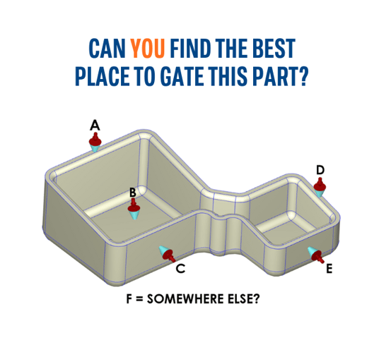
In injection molding, parting lines serve as the foundation for gate placement, providing a clear boundary between mold halves. Options A and D align with this principle, allowing for efficient gating directly on the parting line. Gating into a wall, as in option B, is an alternative but may necessitate post-machining to remove the sprue and well. Since they are not on the parting line, options C and E can be instantly eliminated.
Furthermore, gating directly on the parting line offers advantages beyond simplicity. It facilitates efficient material flow, reduces the risk of defects like flow lines, and minimizes the need for additional features to conceal gate scars. By prioritizing parting line gating, engineers can streamline the injection molding process and optimize part quality.
Sizing Up the Part
Part size plays a crucial role in gate selection, influencing the distribution of material and the efficiency of filling. For larger parts, gating at the center provides a balanced flow pattern, ensuring uniform filling and minimizing the risk of voids or incomplete sections. In contrast, smaller parts offer more flexibility in gate placement, allowing engineers to explore alternative gating locations based on functional requirements and mold design constraints.
Moreover, the size of the part directly impacts cooling rates and cycle times. Larger parts tend to retain heat longer, requiring extended cooling periods to achieve sufficient solidification. Engineers must consider these thermal dynamics when selecting gate locations to optimize cycle times and maximize productivity. By tailoring gate placement to accommodate part size and geometry, engineers can achieve optimal molding efficiency and part quality.
The Material Matters
Material selection is a critical factor in injection molding, influencing flow behavior, shrinkage characteristics, and mechanical properties. Unfilled materials offer predictable flow patterns and uniform shrinkage, simplifying gate selection and mold design. Conversely, filled materials, such as fiber-reinforced polymers such as HX5®, introduce complexities due to directional shrinkage and anisotropic properties.
When gating filled materials, engineers must consider fiber orientation and flow direction to minimize the risk of defects like fiber pull and warping. Strategic gate placement can leverage material properties to enhance part performance and durability. By understanding the unique characteristics of different materials and their implications for injection molding, engineers can make informed decisions to optimize gate selection and achieve desired part outcomes.
Understanding the Injection Molding Cycle
Before diving into gate selection, it's crucial to have a holistic understanding of the injection molding cycle. The primary stages—clamping, injection, cooling, and ejection—form the foundation of this engineering process. Each stage influences the next, emphasizing the importance of a well-coordinated strategy.
Common Challenges and Defects
No engineering problem is flawless, and neither is the injection molding process. Be aware of potential pitfalls, such as sink marks, flow lines, warping, surface delamination, short shots, and jetting. Recognizing these challenges allows you to address them proactively, ensuring a smoother injection molding process.
Conclusion
So where would we gate that part? Without some critical information, there’s really no right answer. Choosing the right gate location in injection molding is a technical challenge that requires a balance of know-how and practical intuition. Parting lines, part size, and material characteristics all play critical roles in solving this engineering puzzle. By incorporating insights from industry experts and adhering to best practices, you can master the technical aspects of gate selection, ensuring an efficient solution in the world of injection molding.

.png?height=383&name=Blog%20Photos%20(10).png)
-1.png?height=383&name=Blog%20Photos%20(6)-1.png)


