As technology advances engineering and manufacturing processes, two powerful simulation techniques, Mold Flow Analysis and Finite Element Analysis (FEA), have emerged as indispensable tools for engineers and manufacturers. These computational methods offer deep insights into the behavior of plastic components during the injection molding process and their performance under various conditions. Combining these techniques allows engineers to optimize designs, improve structure, and minimize costly physical iterations.
Understanding Mold Flow Analysis
Mold flow analysis is a vital tool in the field of plastic injection molding, providing valuable insights into the behavior of molten plastic within a mold cavity. This simulation-based technique enables engineers and manufacturers to predict and optimize the manufacturing process, ensuring the production of high-quality plastic parts with reduced costs and improved efficiency.
At its core, mold flow analysis is a computer-aided engineering (CAE) process that utilizes sophisticated software algorithms to simulate the flow of molten plastic during injection molding. The software considers various factors such as material properties, mold design, processing conditions, and part geometry to create a virtual representation of the injection molding process.
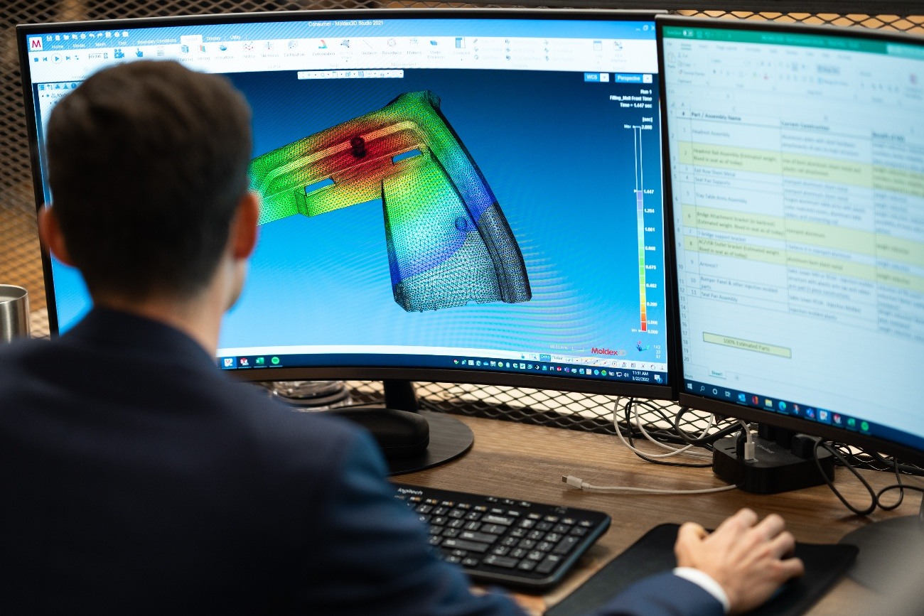
The analysis begins by importing the plastic part’s 3D computer-aided design (CAD) model and the corresponding mold design into the mold flow simulation software. Engineers then define the material properties, including melt flow behavior, viscosity, thermal conductivity, etc. Additionally, they specify the injection molding machine settings, such as injection speed, temperature, and pressure profiles. Once all the parameters are set, the software runs the simulation, simulating the filling, packing, cooling, and ejection stages of the injection molding process. During the simulation, the software generates visualizations, such as flow fronts, pressure distribution, temperature profiles, and cooling rates, to illustrate how the plastic material behaves within the mold.

Mold flow analysis ensures the part is completely filled.

Mold flow also shows fiber orientation within the part, which is the main input for FEA.
The insights from mold flow analysis are invaluable for making informed decisions during the design and manufacturing phases. Engineers can identify potential issues like air traps, weld lines, handling conditions, and warpage early in development; this allows them to optimize the part and mold design to avoid these defects. They can also optimize gate locations, runner systems, and cooling channels to achieve better part quality and reduce cycle times. Through mold flow analysis, manufacturers can minimize material waste, reduce production costs, and ensure the overall success of the injection molding process. Moreover, it is especially crucial for complex parts of high-precision applications, where even minor defects can have significant implications.
In a case study conducted by Plastic Mould, the use of Moldflow technology addressed the issue of plastic steering wheel parts cracking easily. As the product was made of ABS+PC plastic with a two-piece mold, the main problem was identifying high residual stress and uneven shrinkage. The analysis of the issue revealed that the cracking occurred because the product structure separated from the embedded metal skeleton during the filling process. Trapped air at the bottom of the boss caused high pressure, leading to residual stress inside the product. Additionally, the volume shrinkage at the break area was smaller, resulting in internal stress and eventual product fracture.
To improve this design, the team modified the product by changing the angle of the boss and eliminating air trapping. The volumetric contraction difference reduces, and the new products underwent successful testing for high and low temperatures, showing no cracks and improved performance compared to the original products. The study concluded that predicting product quality early in development and optimizing product structure with mold flow analysis can prevent quality issues during production and minimize costly expenses.
Exploring Finite Element Analysis
Finite Element Analysis (FEA) is a widely used numerical simulation technique in engineering and applied sciences that helps analyze complex structures and systems by dividing them into smaller, manageable elements. This powerful computational method allows engineers and researchers to understand the behavior and performance of various components under different conditions without the need for costly and time-consuming physical testing.

FEA simulates common stresses on the part to indicate where designs must be enhanced.
FEA is based on the concept of discretization, where a continuous structure or system is broken down into a finite number of interconnected elements. These elements can be simple shapes like triangles or quadrilaterals in 2D problems or tetrahedrons and hexahedrons in 3D problems. By applying fundamental laws of physics and mathematics to these individual elements, FEA creates a system of equations that describe the overall behavior of the entire structure.
The FEA process begins by creating a CAD model of the component or system to be analyzed. This 3D model defines the geometry and material properties of the structure and serves as the basis for generating the finite element mesh. The mesh represents the discrete elements that approximate the original continuous model. Engineers assign appropriate material properties and boundary conditions to the elements to help define how the structure interacts with its environment, which may involve fixing specific points, applying loads, or simulating various constraints. Once the model is set, the FEA software applies numerical methods to solve the governing equations for each element. The software calculates the displacements, stresses, strains, and other relevant parameters through the structure. With the resulting data, the structure provides a comprehensive understanding of its performance under various conditions.

Photo credit: Hi-Tech FEA
Hi-Tech conducted a case study for a client who is a leading Detection Systems solution provider. The client faced challenges in meeting industry demands and high customer satisfaction expectations while minimizing the number of prototype tests. To address these concerns, FEA was employed to help shorten the design cycle for a Thermal Radiation Detector System used in power plants. The solution involved creating a detailed 3D FEA model using ANSYS v13.0 Mechanical Module and Solid Works Software. The analysis helped determine the maximum temperature of the detector during extreme thermal conditions, enabling the modification of the design to withstand such scenarios. Employing FEA methodology allowed the company to optimize the filtration area and reduce the number of prototypes needed for testing, resulting in increased output and a significantly shortened product development cycle.
FEA stands as a pivotal and versatile tool that empowers engineers to unravel complex challenges, optimize designs, and ensure the integrity and performance of a component in an ever-evolving technological landscape.
Leveraging Mold Flow Analysis and FEA
The integration of mold flow analysis and FEA is a synergistic approach that empowers engineers to gain deeper insights into the behavior of plastic components during and after the injection molding process. Combining these two simulation techniques allows manufacturers to optimize product designs, enhance structural integrity, and minimize defects, resulting in more robust and efficient plastic components.
Starting with mold flow analysis, engineers gain insight into how the plastic material will behave during the injection molding process. The output from mold flow analysis serves as a critical input for FEA. Data from mold flow analysis defines the material properties and initial conditions in the FEA software. The FEA model then accurately represents the properties and behavior of the plastic component as it transitions from a molten state to a solidified product.
Although mold flow analysis and FEA are commonly used as independent processes, combining both techniques will likely become more seamless and sophisticated as more engineers adopt this design process. With these two approaches, engineers can further observe the entire lifecycle of plastic components – from the injection molding process to their performance in real-world conditions.
Coupling mold flow analysis and FEA helps evaluate the true anisotropic performance of parts. At Alpine Advanced Materials, we have an analytical workflow where the fiber orientation of a part is extracted from mold flow and used as a boundary condition for mechanical analysis. However, the benefits of this coupling technique extend beyond just assessing the mechanical properties of a part. These properties can vary drastically if the fibers are oriented in different directions due to the anisotropic nature of the material. Understanding the anisotropic performance helps predict potential failure modes specific to the orientation of the fibers. Combining mold flow analysis and FEA helps engineers understand how the fiber orientation impacts the mechanical behavior of the composite part under various loads and conditions before moving forward to manufacturing processes.
Together, MFA and FEA play a pivotal role in minimizing engineering design risk, particularly when developing steel tools for injection molding, where costs are high, and precision is paramount. MFA helps to uncover any potential issues before tool fabrication and ensures that the final tool design is optimized for efficient and defect-free production. Additionally, FEA allows engineers to make necessary design adjustments for enhanced durability and longevity of the finished part. Both MFA and FEA serve as invaluable tools in the pre-production phase, allowing engineers to refine and optimize tool designs, reducing costly iterations and ensuring that the final steel tool will be the most effective and reliable solution possible, thereby significantly mitigating design-related risks.

Future Trends and Innovations
Alpine Advanced Materials is developing a hybrid overmolding process, focusing on overmolding CFRP (Carbon Fiber Reinforced Polymer) with a thermoplastic such as HX5, a unique material touting inherent strength comparable to 6000-series aluminum at half the weight. Alpine uses this over-molding process to produce components that not only harness the scalability, repeatability, and functional properties of HX5 via injection molding, but also the enhanced strength from CFRP. This innovative approach aims to create components with strength comparable to the targe replacement metal, whether it is 7000-series aluminum, titanium, or steel, but at a significantly reduced weight and faster manufacturing rate.
To achieve this, Alpine is developing a workflow combining mold flow analysis and FEA for hybrid overmolding that creates high-fidelity analytical models, enabling engineers to thoroughly evaluate and optimize the design for the best possible performance and durability. The resulting components represent a breakthrough in engineering, offering remarkable strength-to-weight ratios and enhanced manufacturing efficiency.
As technology continues to evolve, the combination of mold flow analysis and FEA is poised to be at the forefront of engineering advancements, driving innovation, and reshaping the future of product development across various industries.

.png?height=383&name=Blog%20Photos%20(10).png)
-1.png?height=383&name=Blog%20Photos%20(6)-1.png)

.png?height=383&name=Blog%20Photos%20(2).png)
